Every byte sets the pins of a cell. Every bit controls a pin.
The standard braille order is used. 0 = all off, 9 = both pins on the top are on, Hex(40)+Hex(80) = both pins on the bottom are on.

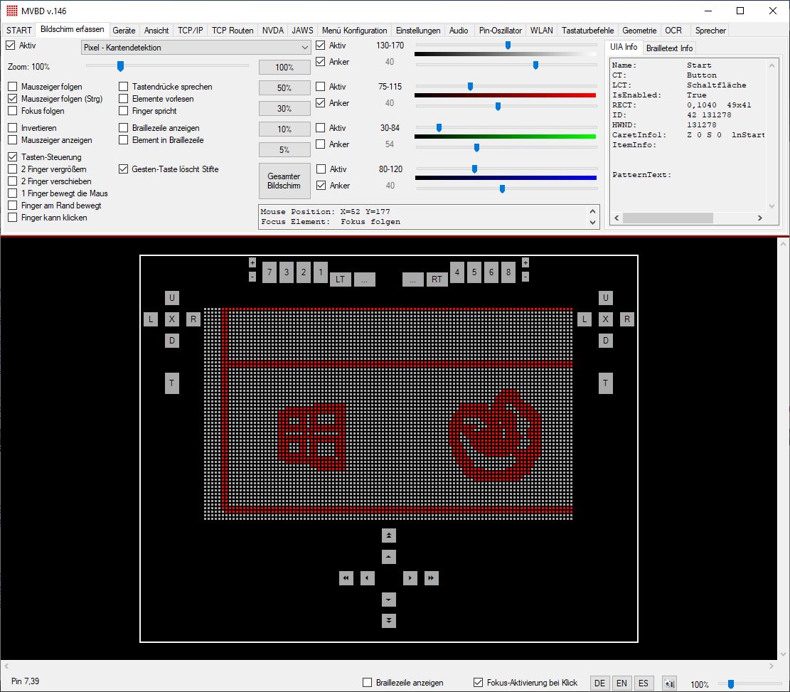
The MVBD (Metec Virtual Braille Device) is a software to control and test all Metec braille devices.
It is possible to do this manual or remote by TCP-IP commands. So you can control the cells from nearly every software of the world.
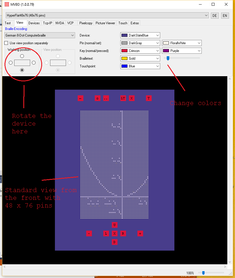
Select your device in the upper left corner. You can use the software as a virtual device too. In this case you don't need a real hardware device.
!!! Since version 140 the MVBD will support only Windows 10 (UWP is used) !!!
Inside the MVBDClient is an example how to control the MVBD.
MVBD.exe (Current version 151)
Windows Driver (only for metec USB controller)
Manual (German only)
Screenshot MVBD
Screenshot working position Front
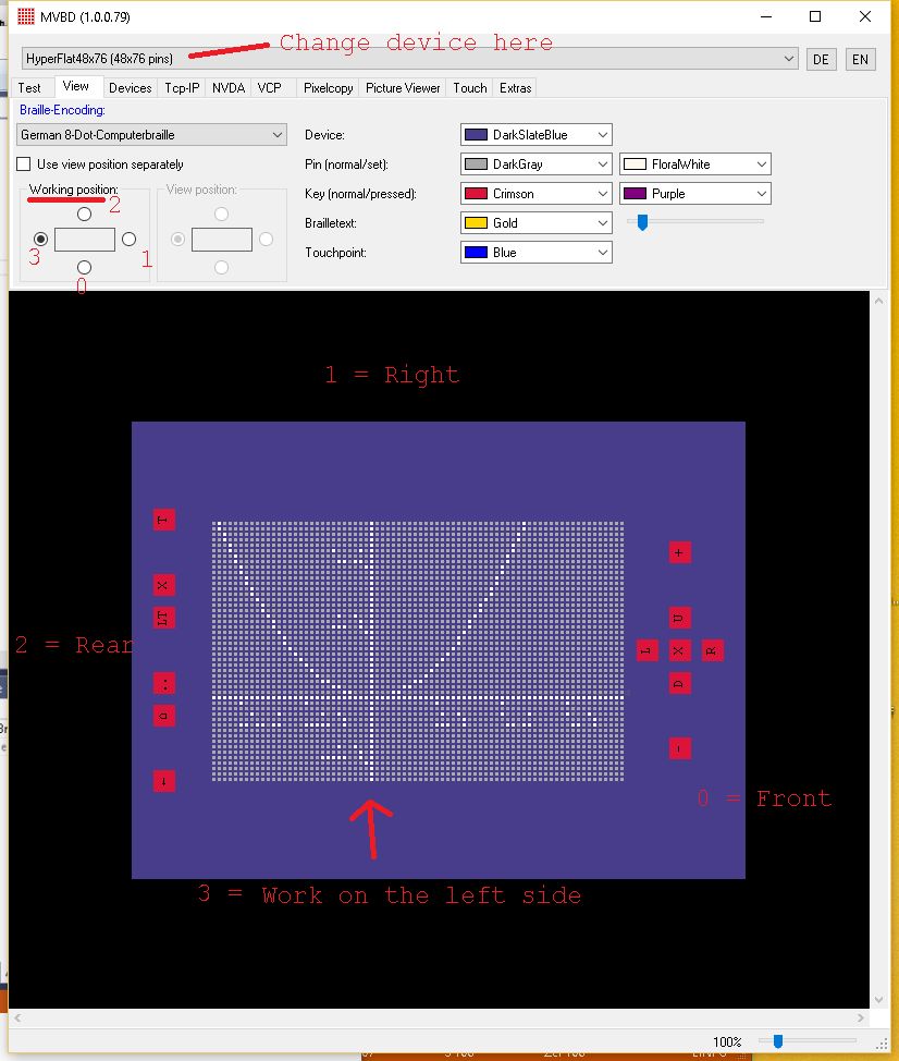
Screenshot working position Left
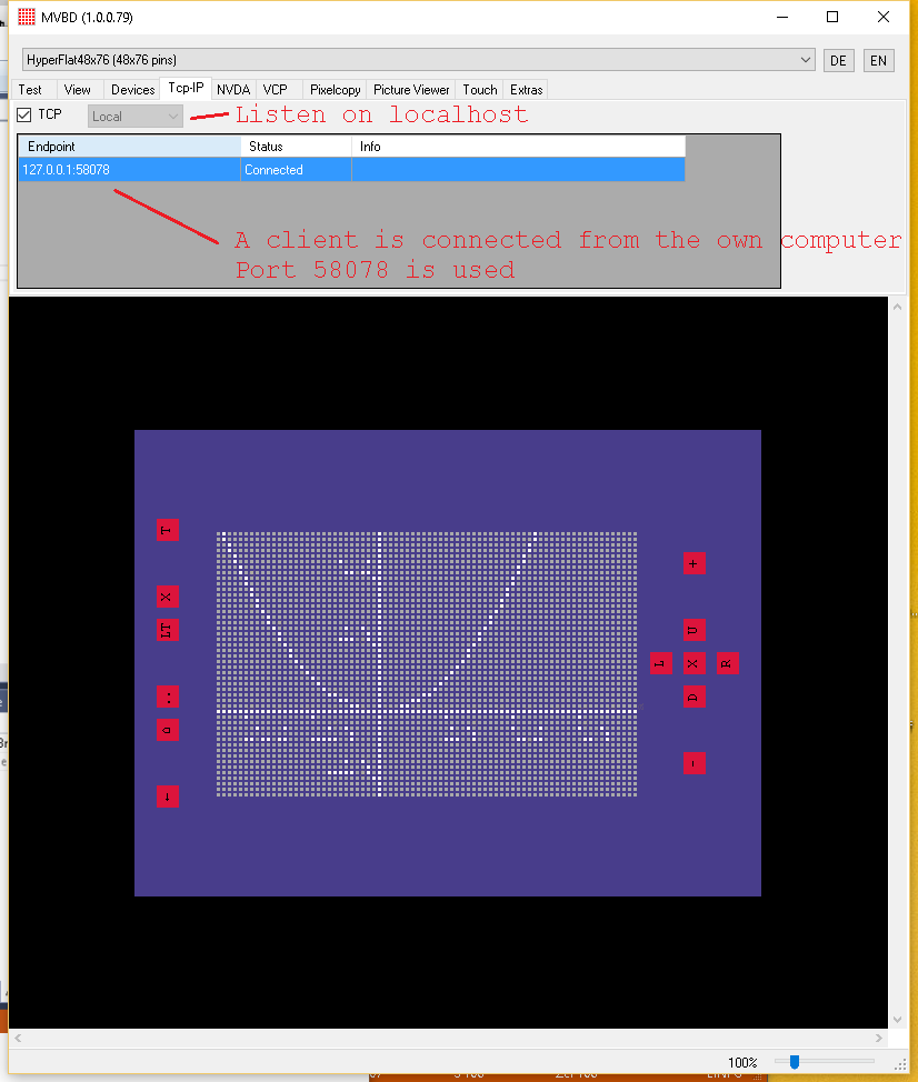
Screenshot TCP client connected
Video Hyperflat
In version 141 of the client you have to tell the MVBD what events (notifications) you want to receive. Look at request 72 SendGetConfigurations and 73 SendSetConfigurations
So the power of controlling the notifications goes back to the clients. The TCP-Rootings (like a firewall) in the MVBD should not be used in the future.
MVBD v.151 New creation of the NVDA AddOn. You can set the last tested version now.
MVBD v.150 Bugfixing. Filling the lists for testing the horizontal und vertical lines
MVBD v.149 Bugfixing. Error when there is no Sounddevice installed
MVBD v.148 Hotfix in the Tcp-IP communication. The header stays at 2 bytes for the length
MVBD v.146 Hotfix Connecting with MRT Box
MVBD v.145 Hotfix Follow Focus and Mouse together. Hotfix HyperBraille F keys
MVBD v.144 Shortcuts deaktivated. Fixed keys in the HyperBrailleF. Keys renamed in Tactile2D and Hyperflat to Function keys 1-6 (Fn1-Fn6). Follow focus shows the element centered. The zoom can be changed by the user.
MVBD v.143 Bugfixing NVDA (2020.2), HyperBraille F cursor keys are synchron now
MVBD v.142 Supports HyperFlat F.
MVBD v.140 (BETA)
OCR with UWP (Windows10 APIs), Spanish, Language independent speakers
Bugfixes for NVDA version 2019.3.1
We need a new version of NVDA addons too. Can be extract in MVBD
Select a device is in a TreeView now. Sorted by groops.
Bugfix on BD III devices. All are overlapped now. Added all BD III variants.
New Tree ComboBox to select a device. BrailleDevices can change the VirtualDevie.
MVBD v.139 Bugfix. Wrong pin order on BD devices (B11 cells). Version 138 and 137 should have this problem.
MVBD v.138 New device BD10 (MRT in black with IAB)
MVBD v.137 FlatPCB is ready and tested. Bugfix BrailleDis
MVBD v.136 New device FlatPCB and Bugfix in PinMoviews file
MVBD v.128 Hotfix. No filter for Bluetooth CoD (Class of Device)
MVBD v.127 Hotfix. If BT name starts with hyperflat the ConnectionTyp is alway BT_Hyperflat
MVBD v.126 Intern. BT-ID for Tactile2D device
MVBD v.125 Sends a DeviceInfo when Show BrailleLine is changed
MVBD v.124 New device Tactile2D
MVBD v.123 Bugfix TcpListener. Automatic start
MVBD v.122 Bugfix if there is no sound defice connected. (Headphones are not connected)
MVBD v.121 HyperBraille F (Ready)
MVBD v.094 Arduino-Serie started(Beta), BD-Blue delay for pin output
Regular the MVBD listen on localhost port
2018. No administrative firewall changes are necessary.
Every request and response has a header of 3 bytes.
Byte 0 is the command
Byte 1 is the low byte of the following length of bytes
Byte 2 is the high byte of the following length of bytes
Maybe in the future we will have new commands or more bytes in the command. So your software should allways read the 3 bytes and the following bytes of data. If you don't know this command ignore it and wait unil the next command is comming.
We are always using Little Endian. The low byte comes first!
Strings will be send and received with a length and UTF8
encoded bytes.
The origin (coordinates) of the pins and touches is top left. We start with 0.
X is the horizontal direction of the standard working position of the device.
So Hyperflat has
a resolution of 48x76, HyperBraille 120x60 and HyperBrailleS 104x60.
After a connect send the command 20 to get the
information of the current device!
Your software should be possible to make a reconnect and catch communication
errors.
Request:
Every byte sets the pins of a cell. Every bit controls a pin.
The standard braille order is used. 0 = all off, 9 = both pins on the top are on, Hex(40)+Hex(80) = both pins on the bottom are on.
Byte 0 is the command (3)
Byte 1 is the low byte of the following length of bytes (5)
Byte 2 is the high byte of the following length of bytes (0)
Byte 3 Cell 1
Byte 4 Cell 2
Byte 5 Cell 3
Byte 6 Cell 4
Byte 7 Cell 5
Request:
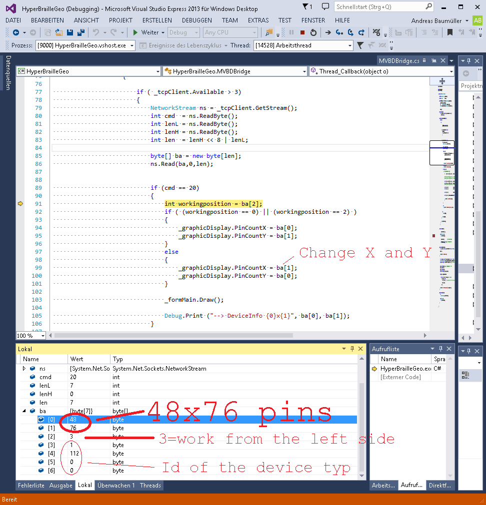
To get the information of the selected device in the MVBD send 20,0,0
Response:
The MVBD asweres with 20,7,0 in the header and 7 Bytes of data
Byte 0: Width. Count of usable horizontal pins (48)
Byte 1: Height. Count of useable vertical pins (76)
Byte 2: Working position. On witch side of the device are you working. (0=Front,
1= Right, 2=Rear, 3=Left)
Byte 3: 4 Bytes of the Id of the selected device typ This ID should not be important for
you.
Byte 4: Id of the device typ
Byte 5: Id of the device typ
Byte 6: Id of the device typ. Highest Byte.
Example
Since version 125 the hight is the usable height. When a braille line is shown a Hyperflat has only a height of 43 dots instead of 48!
Your software should send pins in this resolution.
Request:
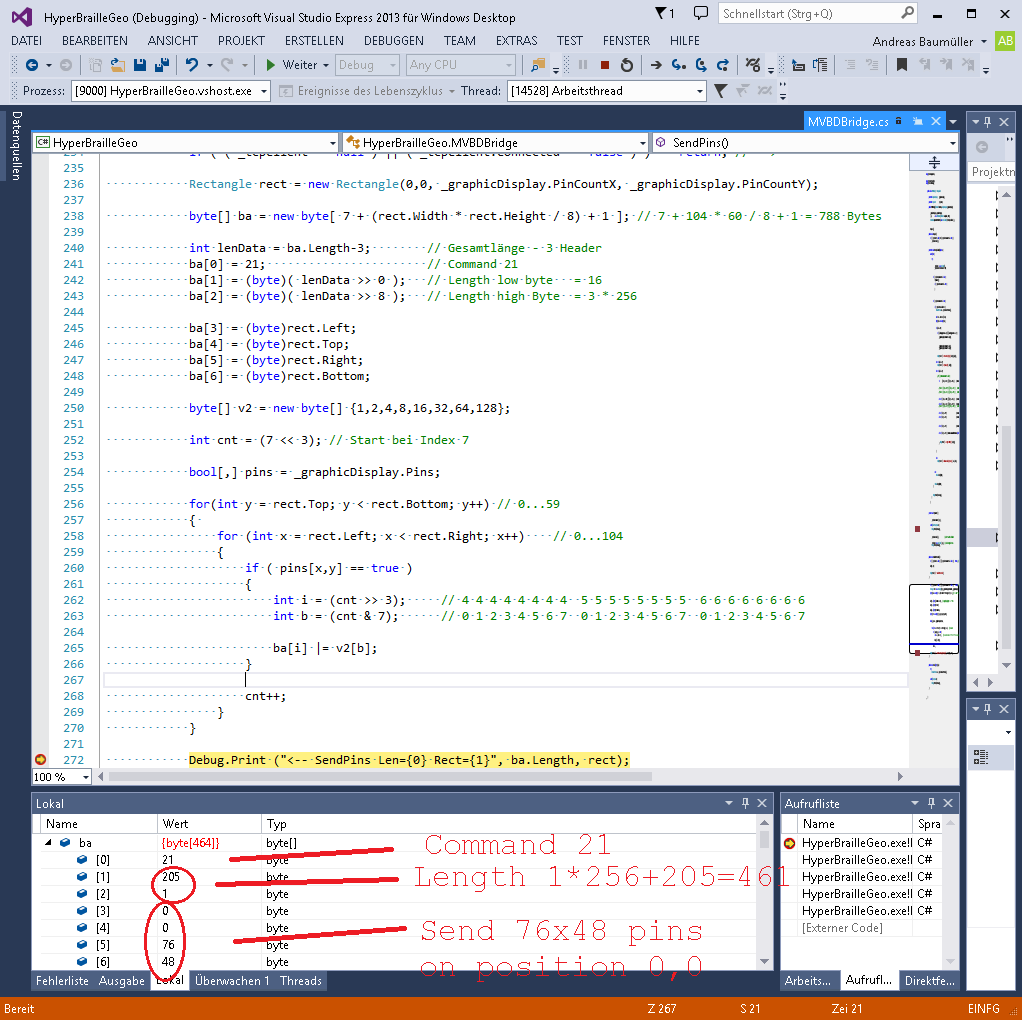
To set pins you can send small parts too. After the header you have to send
rectange data (x,y,width,height) to set the area you want to set. Then are
comming the pins.
Everey pin is a bit. The order is line by line from top to bottom.
We use Little Endian. So the first pin is the value 1 in the byte.
Byte 0 is the command (21)
Byte 1 is the low byte of the following length of bytes
Byte 2 is the high byte of the following length of bytes
Byte 3 Left of the rectangle (0)
Byte 4 Top of the rectangle (0)
Byte 5 Width of the rectangle (76)
Byte 6 Height of the rectangle (48)
Byte 7 Data of the pins. The count is (width * height / 8)
+ 1
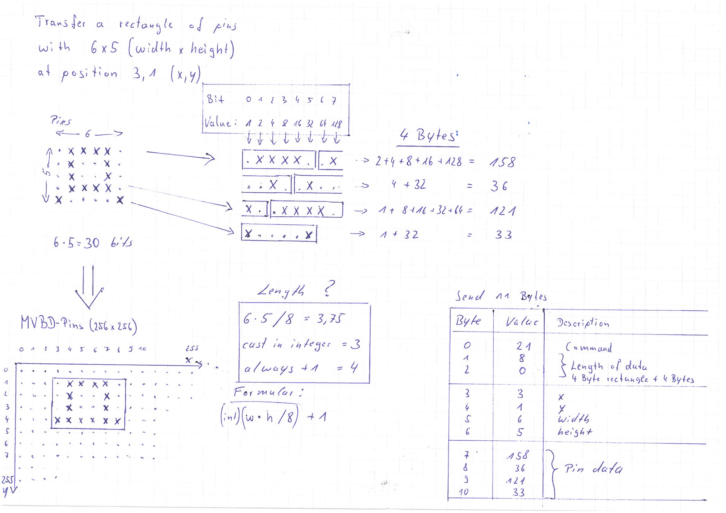
Example
Drawing 6 x 5 pins at position 3,1
This message comes like a event when a key is pressed. There are key numbers like the virtual keys in Windows.For example the cursor Up key has the number 208. Everey device uses this number. Some devices has a second cursor cross. So you can receive 208 for the left Up key and 216 for the right Up key.
Request:
None
Response:
Byte 0 is the command (22)
Byte 1 is the low byte of the following length of bytes
(1)
Byte 2 is the high byte of the following length of bytes
(0)
Byte 3 is the key code
Example
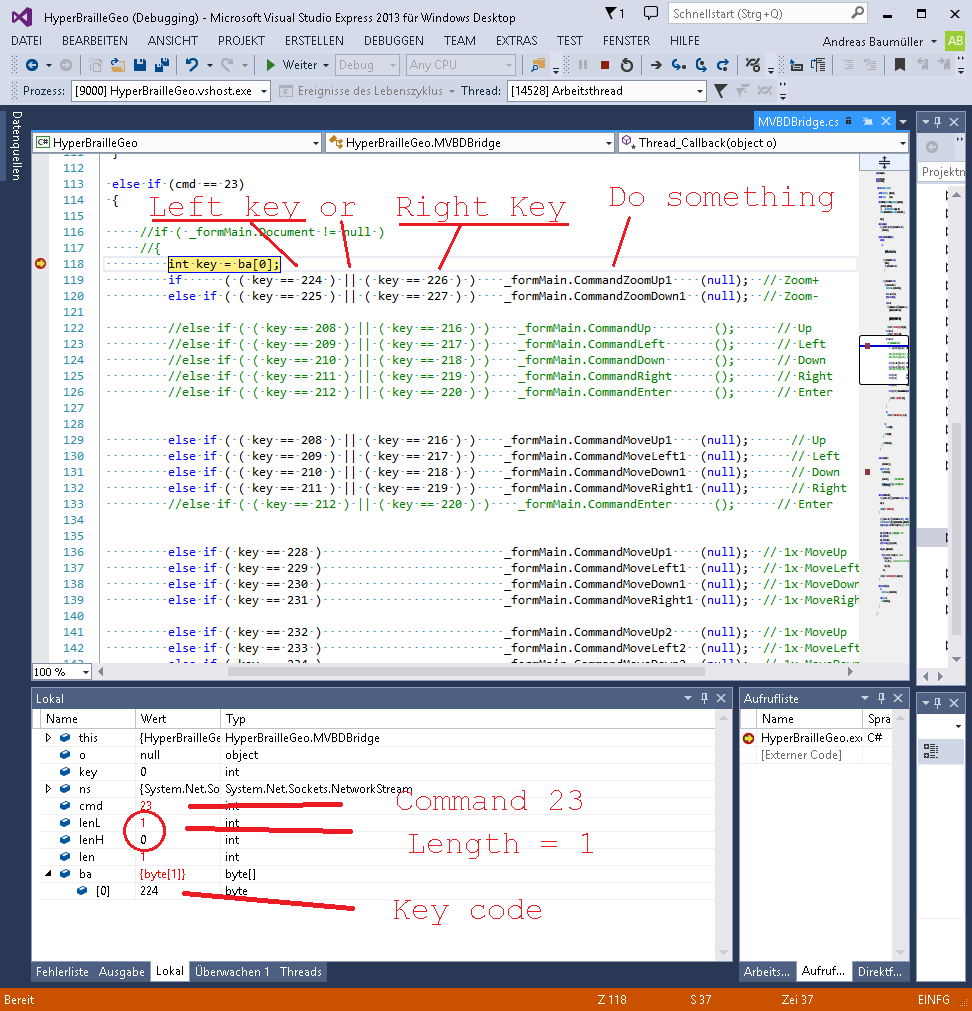
This message comes like a event when goes up.
Request:
None
Response:
Byte 0 is the command (23)
Byte 1 is the low byte of the following length of bytes
(1)
Byte 2 is the high byte of the following length of bytes
(0)
Byte 3 is the key code
This message comes like a event when a finger gets contact, moves or leaves the tactile area.
Response:
Byte 0 is the command (24)
Byte 1 is the low byte of the following length of bytes (7)
Byte 2 is the high byte of the following length of bytes (0)
Byte 3 bit 0-6 is the number of the finger (0-9). When bit 7 (128) is set, the finger has contact, else the finger leaves
Byte 4 X-position of the finger in pin units (Hyperflat: 0-75)
Byte 5 Y-position of the finger in pin units (Hyperflat: 0-47)
Byte 6 high resolution X-positionin of the finger (low byte)
Byte 7 high resolution X-positionin of the finger (high byte)
Byte 8 high resolution Y-positionin of the finger (low byte)
Byte 9 high resolution Y-positionin of the finger (high byte)
This message sets the PWM Value in some special devices. For example BD4_PWM
Request:
Byte 0 is the command (28)
Byte 1 is the low byte of the following length of bytes (1)
Byte 2 is the high byte of the following length of bytes (0)
Byte 3 is the Value from 0 to 7
This message tells the MVBD which type of client is connected.
Available since version 106. Look at Tcp rootings too.
Request:
Byte 0 is the command (29)
Byte 1 is the low byte of the following length of bytes (1)
Byte 2 is the high byte of the following length of bytes (0)
Byte 3 0=Unknown, 1=NVDA screenreader, 2=GRANT application
This message tells the NVDA screenread which action is to do. Like move cursor up, say date.
Available since version 106.
Request:
Byte 0 is the command (30)
Byte 1 is the low byte of the following length of bytes (4)
Byte 2 is the high byte of the following length of bytes (0)
Byte 3 id of the NVDA command
Byte 4 routingIndex (0-39)
Byte 5 dots for braille keyboard (1=a)
Byte 6 space
Examples:
Use the routingIndex to set the cursor to the first cell: 0, 0, 255, 255
Use the routingIndex to set the cursor to the second cell: 0, 1, 255, 255
Press left key: 21, 255, 255, 255
Press up key: 22, 255, 255, 255
Press right key: 23, 255, 255, 255
Press down key: 24, 255, 255, 255
Press enter key: 43, 255, 255, 255
Speak date and time: 64, 255, 255, 255
Press a key: 255, 255,1, 255
This command was made for MRT and MEG applications. NVDA use it too.
Request:Byte 0 is the command (3)
Byte 1 is the low byte of the following length of bytes (5)
Byte 2 is the high byte of the following length of bytes (0)
Byte 3 cell 0
Byte 4 cell 1
Byte 5 cell 2
Byte 6 cell 3
Byte 6 cell 4
values of dots (every dot in a cell is a bit in the byte)
----------------------------------------------------------------------------
byte 0          byte 1          byte 2          byte 3          byte 4
connector 1     connector 2     connector 3     connector 4     connector 5
----------------------------------------------------------------------------
 1 oo 8          1 oo 8          1 oo 8          1 oo 8          1 oo 8
 2 oo 16         2 oo 16         2 oo 16         2 oo 16         2 oo 16
 4 oo 32         4 oo 32         4 oo 32         4 oo 32         4 oo 32
64 oo 128       64 oo 128       64 oo 128       64 oo 128       64 oo 128
----------------------------------------------------------------------------
0 = all pins down, 255 = all pins set
1+2+4+64    = set left pins
8+16+32+128 = set right pins
This command was made for MRT and MEG applications.
Request:Byte 0 is the command (5)
Byte 1 is the low byte of the following length of bytes (1)
Byte 2 is the high byte of the following length of bytes (0)
Byte 3 0=off, 1=on
This command was made for MRT and MEG applications. Every call moves the Pin-Player to the next sequence.
Request:Byte 0 is the command (6)
Byte 1 is the low byte of the following length of bytes (0)
Byte 2 is the high byte of the following length of bytes (0)
Request:
To get all Tcp rootings from the MVBD send 31,0,0
Response:
The MVBD asweres with 31,162,0 in the header. The length of data is 162. You will get a 3D boolean array. Every bool is a bit in the LSB order.
The array has 5 commands x 16 in identifier x 16 out identifier.
There is always the same count of in and out identifiers in the array.
There are 2 bytes for the array length (5 and 16). 2 + (5*16*16 / 8 bits) = 162 bytes.
Byte 0: Count of commands in the array. (5)
Byte 1: Count of identifiers in the array. (16)
Byte 2: 8 boolean values as 8 bits from cmd=0, in=0, out=0...7 (LSB: value 1 is the first out=0)
Byte 3: 8 boolean values as 8 bits from cmd=0, in=0, out=8...15
Byte 4: ... cmd=0, in=1, out=0...7
Byte 5: ... cmd=0, in=1, out=8...15
...
Byte 161: ... cmd=15, in=15, out=8...15
Request:
Have a look into the response of command 31. It is the same like this.
You can send all rooting values with the command 32 at once!
Send a the header 32,162,0 to the MVBD. And then the data.
Byte 0: Count of commands in the array. (5)
Byte 1: Count of identifiers in the array. (16)
Byte 2: 8 boolean values as 8 bits from cmd=0, in=0, out=0...7 (LSB: value 1 is the first out=0)
Byte 3: 8 boolean values as 8 bits from cmd=0, in=0, out=8...15
Byte 4: ... cmd=0, in=1, out=0...7
Byte 5: ... cmd=0, in=1, out=8...15
...
Byte 161: ... cmd=15, in=15, out=8...15
Request:
It is possible to set only one value in the Tcp rooting.
Send a the header 33,4,0 to the MVBD. And then the data.
Byte 0: Id of the cmd. (0-4)
Byte 1: Id of the in identifier. (0-15)
Byte 2: Id of the out identifier. (0-15)
Byte 3: The value 0=false, 1=true
We know 5 commands (cmd) 0=Pins, 1=Keys, 2=Fingers, 3=NVDA Gesture, 4=Device Info
And 16 identifiers 0=Unknown, 1=MVBD, 2=NVDA, 3=GRANT, 4=HyperBrailleGeo, 5=Monitor, 6=MATLAB, 7=Presentation, 8=Eprime, 9...15 are for future use or custom use.
(Look at byte 3 in command 29 to set your identifier).
Request:
Send 34,0,0 to the MVBD, to get the version number of the MVBD software. For example it returns 108 in byte 0.
Response:
Byte 0: Version LSB
Byte 1: Version
Byte 2: Version
Byte 3: Version MSB